TruTrak's New Attitude Direction Indicator - ADI
Home
ADI Installation & User Guide
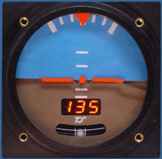
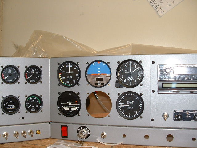
I recently purchased TruTrak's new ADI (Attitude Direction Indicator) for my Rebel instrument panel. When I started the Rebel project I knew that I wanted to have an attitude indicator in the panel, but I also knew that I did not want an AI that operated from a vacuum system. I believed that aircraft vacuum pumps were notoriously un-reliable, expensive, and heavy. At that time my only other choices were an electric AI, or a vacuum AI operating off a venturi tube.
Well, electric AI's are pretty expensive. In the neighborhood of $1910 for a 14V, unlighted RC Allen model. I was finding it difficult to justify (to myself) spending that kind of money for an aircraft that, admittedly, would see mostly day VFR use. That pretty much left me with the venturi tube.
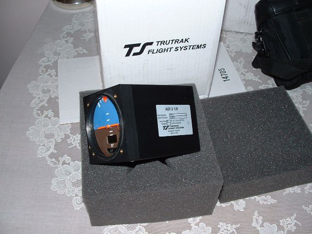
I didn't really like the idea of hanging a big, draggy venturi tube on the fuselage, but I was ready to accept that… until I saw the first advertising for the TruTrak ADI. What great timing! This looked like just what I needed, and wanted! All electronic, no additional remote units, no vacuum system, no venturi, and if I wanted an internal GPS built in it was available. All for $1095 (w/o the internal gps).
.jpg)
.jpg)
.jpg)
.jpg)
I purchased the basic ADI without the internal GPS. This unit can be wired to a panel mounted GPS or a handheld GPS with the appropriate connections. A GPS connection will drive the three digit GROUND TRACK display of the ADI. I intend to wire my Garmin GPS-12XL handheld to do just that. I have located a source for the special plug that fits the back of the Garmin 12XL to which I will be able to supply ships power into the GPS, and serial output from the GPS RS-232 to drive the ADI ground track display.
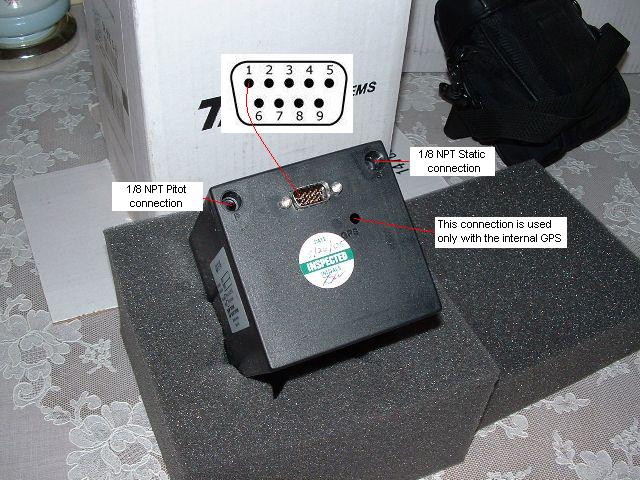
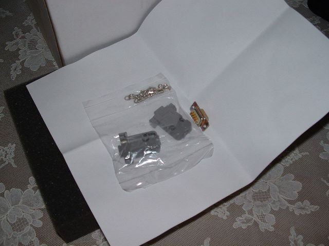
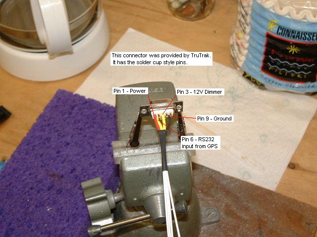
The basic ADI comes with a DB-9 connector kit that will require you to solder wire connections to the back side of the connector pins. In my case I needed to make four such connections. One each for power, ground, dimmer, and RS-232 input from an external GPS. The DB-9 connector provided had the pin numbers marked on the face of the connector. A pinout was provided with the installation instructions.
.jpg)
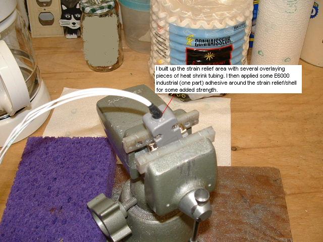
Once the wire connections were made and the connector shell was assembled, I applied some E-6000 single part industrial adhesive around the strain relief just for some added strength and support.
.jpg)
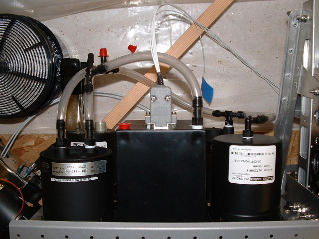
Once the DB-9 was assembled I temporarily installed the unit into the instrument panel. The ADI fits into a standard 31/8" diameter instrument opening. There are two 1/8th NPT fittings on the rear of unit. One is for the pitot connection and one is for the static connection. The installation manual advises that unless the aircraft is pressurized, there is no need to install the static connection. You can just leave it open if you want. I went ahead and made the connections because I couldn't just leave an open hole back there. It needed a proper connection to make it complete to my way of thinking.
.jpg)
I'm still in the process of completing all the panel wiring but as far as the ADI installation goes it all seems very straightforward. If you would like to view the installation manual click on the link above.