How I Installed the Control
Cables In Rebel #687
Part 2-Rudder
Cables
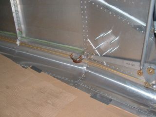
The rudder cables need to pass
through the fuselage skin on each side of the tailcone. Yet the builder's manual
gives us no help in determining where to cut the slot, how big it should be,
shape, etc. A large portion of the time that I spent determining how to install
the control cables, was dedicated to figuring out exactly where I should cut
this slot. I DID NOT want to cut in the wrong location!
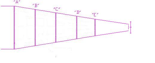
So I taped two large pieces of
kraft paper to the hangar walls. On one I drew a full size line diagram of the
fuselage top view, showing the exact bulkhead locations from Bulkhead A to the
rudder control arm. On the other I drew a full size line diagram of the fuselage
side view, showing the exact bulkhead locations from bulkhead A to the rudder
control arm. These were not extensive drawings, just single line drawings to
show the exact width/height.
Drawings similiar to this.
I made one as if looking at the side, and one as if looking down.
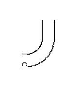
Basically, both were the same except at the rudder control arm. I also made a drawing of the lower bulkhead E radius.
I'll explain why shortly.
This is going to be difficult to
explain from here on, but I'll give it a shot. Before I could figure out where
the rudder cable should exit the tailcone I had to figure out how the cables
would run along the inside of the fuselage. I gave a lot of thought to this
because the builder's manual tells us only to keep the cable as
straight as possible. AC 43.13-B2 tells us that when using cable
guides/fairleads the direction of the cable should not be changed more than 3
degrees.
There are three locations along the
cable run where I could see the cable would change direction more than three
degrees. The transition from the rudder pedal to the first cable guide at the
carrythrough, at bulkhead A, and at bulkhead D.
I seriously considered installing
rudder cable pulleys at bulkhead A and Bulkhead E as some builders have done.
There are several photos of this type installation in the picture archives on
the builder's mail list. While I think this is probably the best way to run the
cables, in the end I decided that many more builders have used the cable
guides/fairleads successfully, and pulleys would just complicate the building
process. I've had enough complications during the building of this
airplane and didn't want any more. So I just decided to use the cable
guides in the best fashion I could.
With that decision made,
I installed the cable guides at the carrythrough, under the mixer arm,
at bulkhead B, and at bulkhead D. By placing cable guides fore and aft of
Bulkhead A you don't get as sharp an angle in the cable.
The other issue here is how high/low
on the fuselage inner wall do I mount the cable guides? If I mount them lower
than the top rivet line of the inner corner wraps, then the cable is being
mounted further inboard due to the radius of the corner wraps. This means that
when the cable turns outward from bulkhead D, the angle outward will be
greater.
So how did I figure all this out? We
need to go back to the two full size drawings.
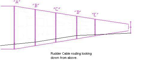
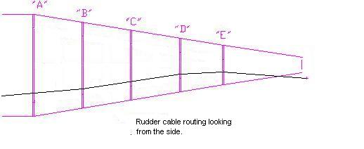
On the (full size)
side view drawing I put a push pin (thumbtack) at the correct height
on bulkhead D and ran a string (depicted as a black line in the above drawings)
to a push pin at the rudder control arm position.
On the top down drawing I put a push
pin on bulkhead D, two inches in from the line representing the outside skin
(two inches is the bulkhead thickness from flange to flange) and ran a string
from this point to the rudder control arm position.
I played with the positioning of the
string on the drawings to try to determine where they should run along the inner
fuselage and how the angles would be as the cable exited to the rudder horn. I
found that the instructions to keep the cable run as straight as possible was
much easier said than done.
As I stated earlier, if you mount the
rudder cable guides low, in the curve of the corner wraps, that increased the
outward angle the cable has to make to exit the fuselage. The higher the rudder
cable guides are mounted in the fuselage, the greater the downward angle the
rudder cable has to make in the tailcone as it exits to the rudder
horn.
I decided that the only logical
compromise was to mount the rudder cable guides along the top of the inner
corner wraps from the carrythrough bulkhead to bulkhead D. In my opinion this
was the point that would minimize both angles the rudder cable would
have to make (downward and outward) as it continued aft of bulkhead D to
the rudder horn.
Back to my drawings. If my full
size drawings are correctly sized, I could (theoretically) obtain measurements
from the drawings of the point where the cable (string) would pass through the
fuselage skin. On the drawings, I marked the point where the string
intersected the line of the fuselage skin, then I measured up
from the bottom skin and aft from the bulkhead E. I transferred these
measurement from the drawings to the aircraft tailcone. What I
found was that because I was taking measurments from one
dimensional drawings and transferring those measurements to a three
dimensional object, the point I was measuring for was actually a
'point in space' outside the fuselage. I determined this was due to
the combination of the curvature and taper of the tailcone.
So, to try to explain a little
more, the fuselage exit point I was measuring for on the drawings actually
turned out to be a 'point in space' just outside the curvature of the outside
bottom corner wrap. At first this kind of threw me, but I surmised
that even though this was a 'point in space', it was still on the path the
actual rudder cable would take. I figured out that I would have to
attach my cable (string) to the rudder horn, pass the string through this
'point in space' that I had measured to and, keeping the string taught, find
where it intersected the fuselage skin and that is where the exit hole would be
located.
I don't think I can adequately
describe how I measured this 'point is space' without totally confusing anyone
reading this. Suffice it to say that, from the full size drawings
I measured from known points, ie; the plane of the outside skins, the
bulkhead line, etc. So, from the drawings determine the distance aft of bulkhead
E (or forward of the solid bulkhead). Transfer that measurement to the fuselage
and mark it. Then go back to the drawing and determine how far above the plane
of the bottom skin the point will be. Using a four foot straight
edge placed vertically against the outside skin at the mark made
previously, and a straight edge against the bottom horizontal skin, measure
up from the intersection of the two straight edges the appropriate distance.
This should be your 'point in space'. Make a note of how far below the
horizontal rivet line the measurement is so that you don't have to use two
straight edges to find it again. All you will need to do then is place the
vertical straight edge against the skin at the aft mark and measure down from
the rivet line.
OK, with the vertical straight edge
in place against the skin at my mark, and my cable (string) attached at the
rudder horn, using my one free hand I run the string taught along the fuselage.
Extend the string forward with the thumb pressing it against the
skin. Keep adjusting it (your thumb) high or low, forward or aft until the
string just touches the vertical straight edge at the known distance below
the horizontal rivet line. Where your thumb is at this point is where you
will cut the slot for the rudder cable to pass through the
fuselage.
But don't start cutting a hole yet
because there is another issue to deal with first.
With the string on the drawings
running straight from bulkhead D to the rudder control horn, the string
indicates it will pass through bulkhead E. The downward angle of the cable
from Bulkhead D also exceeds three degrees. If I
move the string to pass along the inner flange of bulkhead E, the outward angle
of the string to the rudder horn exceeds 3 degrees.
I elected to have the rudder cable
pass through bulkhead E. By doing this I could set a cable guide in bulkhead E
at a position that was slightly higher, and slightly inboard, than a
straight line, thereby easing BOTH angle changes between bulkhead D and the
rudder horn. So I had to move my strings around on the drawings until I had the
angles OK. I transferred these measurements to the drawing that I had made of
the bulkhead radius so I could figure out where on bulkhead E I would need to
drill a hole for the cable to pass through. I then had to recompute the point on
the fuselage where I would have to cut the slot for the cable to pass
through.
Once I believed this would all be OK,
I thought about it more, measured everything else again at least a dozen times,
decided it was as good as it was going to get, and drilled a #30 hole in one
side of the tailcone. Then I drilled a #30 hole in one side of bulkhead E.
I ran my rudder cable (string) the full length, tying it off to the rudder
pedal, through the cable guides, through the hole in the bulkhead E, through the
hole in the tailcone, and tied it off to the rudder horn. I checked the routing
to see how I might need to adjust the hole in the bulkhead E or the tailcone.
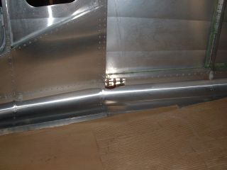
Then I gradually opened up the slot in the tailcone until I was satisfied with
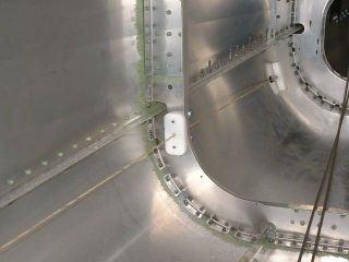
it. And I drilled the hole in the bulkhead E to 1/2 inch diameter to accept my
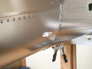
custom made fairlead. But getting back to the tailcone slot, one idea that I saw
and liked on Steve Sloan's and Chuck Bailey's Rebels was a cable guide installed
in the tailcone slot for the rudder cable. I tried a stock cable guide as came
with the kit but didn't like it because it created a sharp bend in the
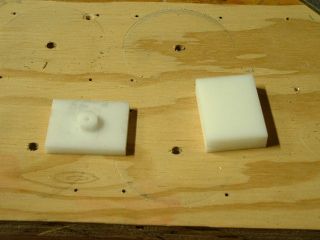
cable. To be usable, I felt it would have to be altered. So I fabricated my own
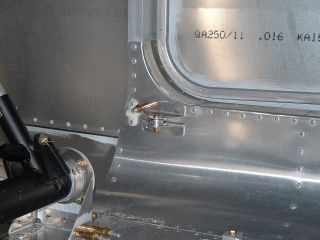
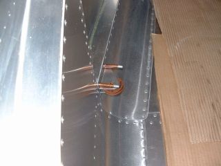
from some delrin stock I had. I also fabricated a fairlead for the bulkhead E
from the same material. See the attached photographs.
After I did all this I had my EAA
Technical Counselor come out for an inspection. He liked the small cable guide I
installed in the slot to isolate movement of the cable as it passes throught the
fuselage skin.
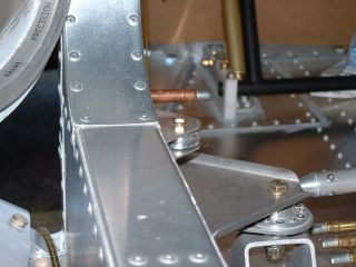
He did not like the angle of the
rudder cable from the rudder pedal to the first cable guide at the carrythrough
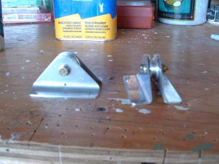
bulkhead. He suggested a small pulley here. He even offered to fabricate the
pulleys on his lathe. So I made up some brackets out of some hefty .063 6061-T6
and used the pulleys he turned from aluminum stock.
I really like how they turned out.
Initially I thought they would be obtrusive, but they really aren't in my
opinion. At least no more obtrusive than the control column torque tube mounted
in the middle of the cabin floor or the mixer arm assembly on the pilot's
side; or the unshielded control cables running through the cabin.
The cable guides at the carrythrough
bulkhead were subsequently removed.
My EAA Technical Counselor also did
not like the angle of the rudder cables past the bulkhead A location and
suggested pulleys here also. I fabricated brackets of .032 6061-T6 and used the
same type pulley that Murphy Aircraft had provided for the elevator
cable/bulkhead D station.
After adding these pulleys, my EAA
Technical Counselor gave a thumbs up to the control cable system! As I said, the
whole affair was just slightly more involved than the builder's manual
instructions to "keep the cable run as straight as possible".
Roger Hoffman
#687R
Eugene, OR
USA