When I was in the process of building the Rebel, I found a 'white paper' while surfing the world wide web, which described how to build your own Lift Reserve Indicator. I did some further web research to learn more about this device. I found an excellent article by Sparky Imeson at Mountain Flying LLC. This article describes his use of the commercially available LRI from Alpha Systems. Another excellent article about installing and flying the InAir Instruments LRI can be found at Sam Buchanan's RV website. These commercial systems typically run several hundred dollars and up. I decided I would like to try an LRI in the Rebel but, not wanting to spend that kind of money for something I could build for a lot less, I opted to go the homebuilt route.
I ordered the Dwyer Minihelic II differential pressure gauge and some aluminum bar stock to fabricate the probe from. I quickly found that trying to drill two, long parallel holes, of small dimensions, through the length of a piece of aluminum bar stock as described in the referenced 'white paper' was not easy. Then, trying to drill two intersecting holes at 45 degrees to the long holes, at the tip of the probe was...well let's just say that after several attempts, I was not happy with my results. Further, I could not figure out how to access the gauge face to apply the colored range markings. The 'white paper' just did not address this. Trying to pry the lens from the housing did not work, nor did screwing the back off the housing. So after all this I put the gauge back into the box and tucked it away on a shelf, where it has remained for several years.
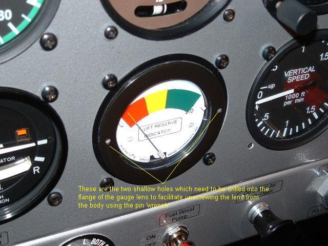
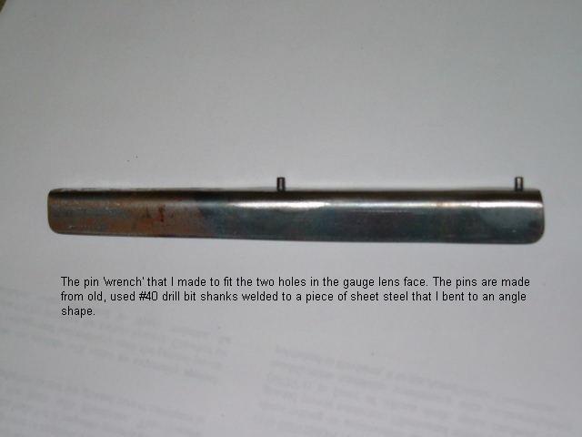
Recently I was back on the web and came across a website that described building the homemade version of the LRI. This website described how to remove the lens from the Dwyer gauge by unscrewing it. During my earlier attempts to remove the lens I had considered it might be screwed into the housing, and had attempted to unscrew it by hand, without success. This new website described drilling two small, shallow holes on opposite sides of the lens face and using a specially made 'wrench' to unscrew the lens from the gauge body. It worked. See my photos for additional detail.
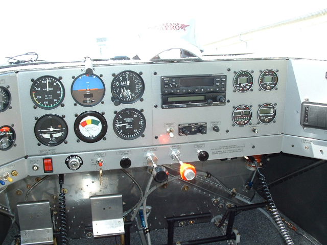
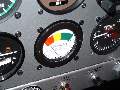
I purchased some automotive striping tape from a local sign shop, cut out the range markings for the gauge, applied them to the gauge face, and quickly had the gauge ready to install in the panel. The gauge is not a standard aircraft size 2 1/4" or 3" diameter so I made an adapter plate from some scrap aluminum to adapt the gauge to a spare 3" instrument hole in my panel.
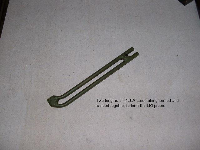
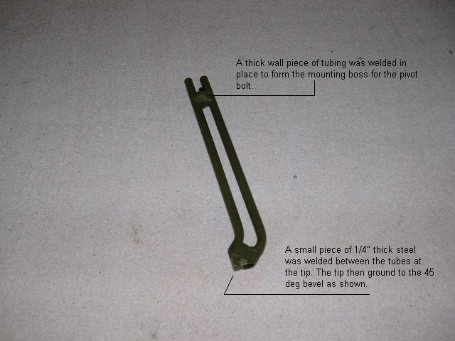
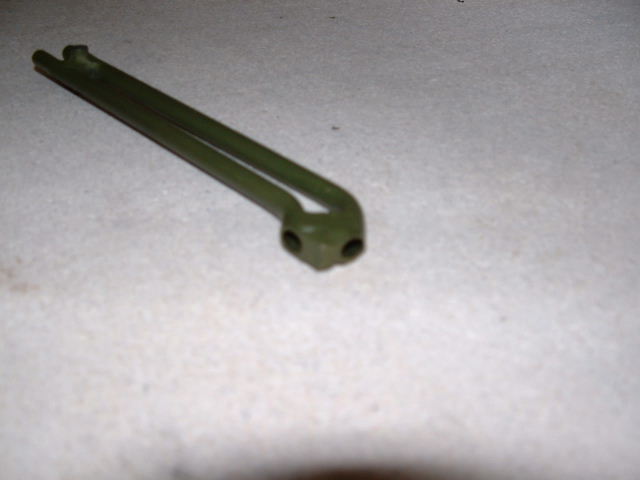
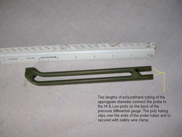
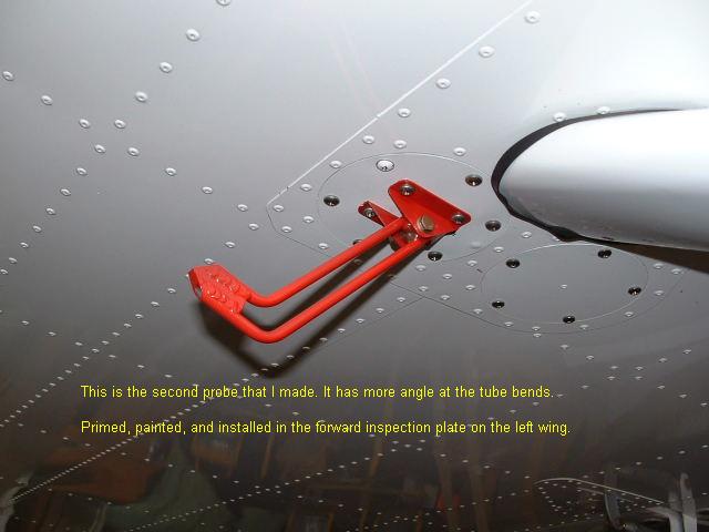
My probe is made from 1/4" dia. thin wall 4130A tubing which I welded together as shown in the accompanying photos. The angle mounts are made from aluminum sheet. I mounted this probe in the forward inspection plate cover on the right wing. This is similiar to my mounting of the pitot tube in the inspection cover on the left wing.
Two poly tubes run from the probe, down the wing strut, into the cabin, behind the instrument panel to the gauge. There are no other connections to be made. I did use some expandable nylon anti-chafe material around the tubing where it runs inside the wing strut.
After several flights to get the probe adjusted I can say that the LRI works as described and that I am very happy with it. It has made me feel much more comfortable and confident when flying at minimum controllable airspeed. Total costs were approximately $60 USD.
Clicking on the thumbnail photos will bring up a larger photo, several of which will have additional narrative attached.